Mechanical Devices
Mechanical Devices
Mechanical movement is the way a structure moves to create movement.
-
Linear motion – Movement in a straight line in one direction. A train uses linear motion to move along a track.
-
Rotary motion – Rotary movement follows a circular path around a centre point such as a bicycle wheel.
-
Reciprocating motion – Reciprocating motion is the movement of in/out, up/down or left/right. Found in a car engines piston.
-
Oscillating motion – The motion of left to right (or backwards) from a single point. Found in a grandfather clocks pendulum.
Levers:
Levers are used to lift loads with the least amount of effort. Placing the fulcrum (or Pivot) (the point which the lever turns) in different places effects where the load can be lifted.
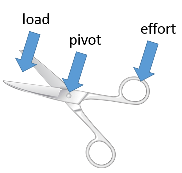
First order (Class 1): The pivot is placed centrally between the force and the load such as a pair of pliers, scissors or a crow bar.
Second order (Class 2): The effort comes first, then the load at the same side of the pivot. Such as a wheelbarrow, where the wheel is the fulcrum.
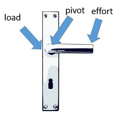
Third order (Class 3): The load is first, effort in the centre and fulcrum at the end. Examples include tweezers, mouse traps and a hammer hammering a nail.
Mechanical advantage is the measure of force when a tool is applied as a lever. Pulleys rely on the relationship of load and effort.
Mechanical Advantage = Load / Effort
Linkages:
Linkages are a mechanism which creates movement around a fixed pivot. They can be used to change the direction of motion, type of motion and the size of a force.
-
Reverse motion linkage – Because the pivot is fixed in the centre of a Z shape when moved the top moves in the opposite direction to the bottom.
-
Parallel motion linkage – Two fixed pivot points vertically make the horizontal movement parallel.
-
Bell crank linkage - A bell crank linkage looks like an L shape with a pivot point in the corner. Horizontal force changes into vertical movement.
Rotary Systems:
Rotary systems use circular movement to move and create power in in an item.
Cams – A Cam and a follower create movement. The follower rests on the cam and moves in the shape of the cam. Circular cams rely on the centre of the circle being offset. A pear cam creates a gentle rise and fall as the follower flows the pear shape, an eccentric cam is a circular cam and a drop (or snail) Cam which lifts gentle then drops down.
Gears – Gears are wheels which interlock to move the force. Different sized gears increase and decrease the speed they turn. Power turned the driver gear clockwise which turns the next gear anticlockwise. If you add a centre gear (called and idler) it turns the gears on either side in the same direction. If gears are different sizes the smaller gears turn faster (if your riding your bike you have to pedal more with your chain on a smaller gear than if it is on a higher gear). Examples such as hand whisks and hand drills use gears. Bevel gears can change the direction of gears by setting them at 90 degrees (as used in a hand drill or tin opener). Circular motion is measured in revolutions per minute.
Pulleys – Pulleys can help lift a load by transferring the weight through a wheel. A single pulley makes something easier to move by pulling down rather than up. Using 2 pulleys can lift a weight using half the effort. Examples would be curtains on a rail or a sewing machine. Velocity ratio is the ratio of the distance moved by the effort to the distance moved by the load. VR=Distance moved by effort/distance moved by load.
Belt drives - Belts can transfer movement from one rotating shaft to another, working like gears a smaller wheel spins faster when attached to a bigger wheel. This is used in washing machines.
Rack and pinion - A circular gear (pinion) uses its teeth to engage in a long bar of teeth (rack) to pull itself along or up, used in a chair lift.