Boolean Logic
Logic Gates
No matter how complicated a computer may appear, in practice it is just a series of switches that are either ON or OFF (represented using 1 and 0). These switches work together with the CPU to do everything that a computer needs to. If the switches are turned OFF and ON in just the right order, we might see an image appear on the screen, or hear our favourite sound from the speakers.
In order for this system to work and the CPU to process what it is required to, there are sequences of logic gates that combine different inputs together. By combining these gates together into logic circuits, the computer is able to make decisions that affect how it performs.
NOT Gate
The simplest of the logic gates is a NOT gate.
This is the symbol for a NOT gate:

The input value (A) is sent through the logic gate and flipped. This means, that if the input is ON (usually we use the number 1 to represent this), then the output will be OFF (or 0).
For any logic gate like this, we can represent what happens for all combinations of inputs by creating a truth table.
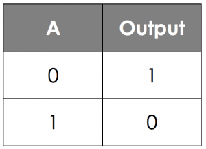
In this table, we are able to see what the output is based on the input.
AND Gate
The next logic gate is an AND gate.
This is the symbol for a AND gate:

Here, we have two input values, A and B, which the output relies on. For an AND gate, the output is only ON (1) if both of the inputs are ON (1). If either of the input values are OFF (0), the output will also be OFF (0).
As before, we can represent this in a truth table, although this time we have to take into account both the possible inputs.
With 2 inputs, there are 4 possible combinations that we could have:
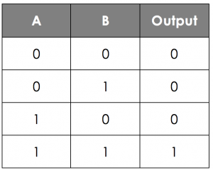
Notice that in this truth table, there is a pattern for the inputs. The column for input B alternates 0,1,0,1 and the column for input A doubles up, 0,0,1,1. By using this technique, it means that we are able to make sure we have every possible input combination.
OR Gate
The third logic gate you need to know about is the OR gate.
This is the symbol for the OR gate:

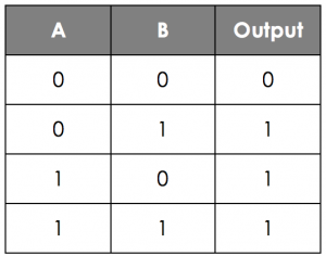
Here, as with the AND gate, we have two inputs A and B. For the OR gate, the output is ON (1) if either of the inputs are ON (1) or even if both are ON (1). Therefore, and OR gate is only OFF (0) if both inputs are OFF (0).
Again, we can use a truth table to represent this:
Logic Circuits
As mentioned before, these logic gates can be combined together to create logic circuits. Here for example, we have a circuit which makes use of 3 inputs to produce a single output value.
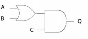
We can actually represent this logic circuit using a logic statement:
Q = (A OR B) AND C
Notice the brackets around the A __OR __B. This is because in the diagram, the OR gate is done first, and like with BIDMAS in maths, logic gates also have a specific order that they are processed in - Brackets always come first!
Truth Tables
As with the single gates, we can use truth tables to represent the output of a logic circuit depending on different inputs.
Here for example is a logic circuit using two inputs and two gates:
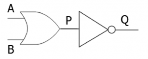
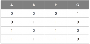
When creating a logic table for a circuit like this, it is a good idea to put in steps in the middle so you don’t have to work out the whole circuit in one go. In the example above, you can see that there is an extra letter P in the middle of the circuit.
We can use this to complete our truth table:
If we have our three input circuit like we have to the left, then we are going to need a new way of writing out all of the inputs. As before, for the column on the furthest right, you should alternate the values, (0,1,0,1 etc). Then in the next column over double them up (0,0,1,1 etc.).
In the furthest left column, you should now quadruple them up as below:
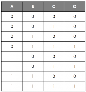
In this example, you can see that no intermediate values have been used. This is the table you’d be expected to produce in your exam - but that doesn’t mean you can’t do the working out beforehand using the intermediate steps!
Logic Diagrams
You saw above that you can draw logic gates into logic circuits. One of the things you will be expected to do is to create logic diagrams from logic statements.
For example, draw the logic diagram for the statement Q = NOT (A AND B).
Steps to follow:
- Draw the inputs and outputs first
- Add the gate inside the innermost brackets
- Work your way out of the brackets, adding in gates as you need to
- Join the inputs and gate outputs together
- What is the logic statement for this circuit?
- Your answer should include: Q / NOT / A / OR / B
Hints When Drawing Diagrams
- Use a pencil for drawings - it’s much easier to correct any mistakes.
- Always start with the brackets.
- Make sure that it is very clear which gate you are using - an AND gate has a flat edge.
- Try to use horizontal and vertical lines to join your inputs and gates, not diagonal ones.
- Make sure you label all of your inputs and outputs.
What is the missing value in these diagrams?
- Q:
- 0
- A:
- 1
- A:
- 0
- What is the correct logic statement for this logic circuit? (1, 2, 3 or 4?)Q = (A OR B) AND CQ = (A AND B) OR CQ = A OR (B AND C)Q = A AND (B OR C)
- 3