Electric Circuits
Electrical Components
Warning: This lesson might include some technical words without definition. These will be covered in subsequent lessons in this topic, though feel free to do a cheeky google yourself first!

(LDR = Light dependent resistor)
(LED = Light emitting diode)
You need to be able to recognise and draw each and every one of these circuit symbols.
Each component has a different function:
- Switch (Open or Closed): Switches are used as an easy way to make or break a circuit, turning it on or off.
- Cell: Cells give power to the circuit, they store chemical energy. In everyday life, lots of people incorrectly call these batteries.
- Battery: Batteries are two or more cells in a circuit together.
- Diode: A diode only allows the current to flow one way. There are different types of diode, one of which we will meet later on.
- Resistor: A resistor provides a constant resistance to the circuit. This is important if you want to have a specific current or potential difference running through other components in the circuit.
- Variable Resistor: A resistor where you can change its resistance. They often have a dial to allow the resistance to be changed.
- LED: This stands for a light emitting diode. Remember what a diode does? This is a special kind of diode which releases light. LEDs are often used in torches and lights in a home.
- Lamp: Also known as a bulb and releases light when energy passes through it.
- Fuse: A fuse is a safety component. If the current becomes to high, it melts and breaks the circuit preventing a fire or damage. This is discussed in more detail in a further lesson.
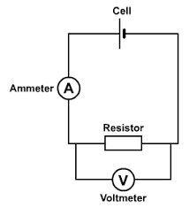
- Voltmeter: Used to measure potential difference, this is always placed in parallel
- Ammeter: Used to measure current, this is always placed in series.
- Thermistor: A resistor changes its resistance according to its temperature. This is discussed in more detail in a further lesson.
- LDR: Light dependent resistor. This resistor changes its resistance according to how much light is shone onto it. This is discussed in more detail in a further lesson.
- Motor: Converts the chemical energy from the circuit into kinetic energy
Drawing circuits is relatively simple so long as you follow the following general rules:
- Read the instructions carefully!!! I cannot tell you how many times students do not read the question properly and get it wrong.
- Reread rule 1!
- Use a ruler
- Always ensure that there is either a battery or a cell drawn correctly.
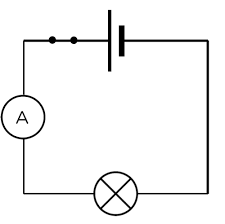
- If an ammeter is required, always draw it as part of the same loop as the battery/cell.
- If a voltmeter is required, draw it around the component that you need to measure e.g. bulb or resistor
Series and Parallel
A series circuit is a circuit with only one loop:
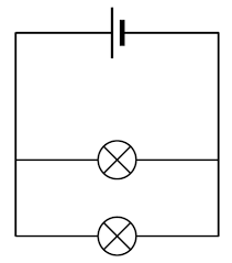
A parallel circuit is a circuit with multiple loops:
Voltmeters
Potential difference is the energy transferred per unit charge. This means that if we have a battery of 5V, it gives every electron 5J of energy.
Voltmeters are always connected in parallel around the component as shown below.
Energy
You need to be able to recall and use the following equation:
E = Q x V
- E - Energy (Joules, J)
- Q - Charge (Coulombs, C)
- V - Potential Difference (Volts, V)
- What is the difference between a series and parallel circuit?
- Your answer should include: one loop / multiple loops
Explanation: Series only has one loop Parallel has multiple/more than one loop - A voltmeter is placed around a bulb and it measure 10V. How much energy is each electron giving to the bulb?
- 10J
- Calculate the charge of a battery that gives 30J of energy to the circuit and has a potential difference of 25V
- 1.2C