Telescopes
Large Telescopes
Resolution
When light enters a telescope, it is passing through a gap. It spreads out by the process of diffraction.
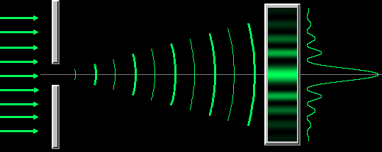
Fraunhofer diffraction also occurs with circular openings. If we use a circular aperture we get an effect like this:
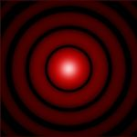
The bright spot in the middle is called at airy disk.
Rayleigh Criterion
The angle of separation between the fringes is called the Rayleigh criterion:
[θ - angular separation (rad); λ- wavelength (m); D - aperture width (m)]
To improve the resolution of a telescope, we need to have a large aperture and a short wavelength.
In practice, although telescopes have much better resolution that the eye, this is limited by the atmosphere. Telescopes have large apertures to allow as much light to get in as possible.
The collecting power of a telescope is proportional to the diameter squared.
Eyes and CCD
Coupled charged devices or CCDs are often used for detectors. They have millions of pixels packed onto a detector the size of a postage stamp.
• They are sensitive;
• Their quantum efficiency is about 70%. A film has a quantum efficiency of about 4% which means that 25 photons are needed to deposit a grain of silver. The eye only has a quantum efficiency of 1%.
• They are getting cheaper all the time.
• The CCD can detect radiations that are beyond the visible spectrum

Lenses
Ray Diagrams
Recall drawing ray diagrams through lens’s at GCSE (Triple content only)
Below, are the basic lens diagrams, you need to be familiar with these before moving onto our ray diagrams inside a telescope.
We can determine where an image lies in relation to the objects by using a ray diagram. We can do this by using two simple rules:
Where the two rays meet, that is where the image is found.
The diagrams show how we do a ray diagram step-by-step:
This diagram shows where an object is at a distance of greater than twice the focal length. The image is inverted (upside down), real, and __enlarged __(bigger).
The lens formula is:
Where
f = focal length
u = length between object and the lens
v = length between lens and the image
Inside a telescope there is an objective lens and an eyepiece lens, similar in use to that of a microscope.
The objective lens makes a small real image of the object while the eyepiece lens acts as a magnifying glass. The following factors are important in making a good quality instrument:
The telescope is in normal adjustment because the image is formed at infinity, ie the light rays leave the telescope parallel. This means that the focal points of the two lenses coincide, making the distance between them equal to the sum of the focal lengths.
The diagram includes the intermediate image (at the point where the two focal points coincide), but isn’t essential. Try to avoid the following common problems with the diagram:
Make sure that you understand that the three parallel rays come from the same point on the object, ie the rays may not be parallel in reality - but are too close to being parallel as to make any difference.
Angular Magnification
The magnification that the image undergoes is:
Drawing the above diagram is a common question, so make sure you can do it!
Focal Length
The magnification can also be calculated via the focal lengths:
Reflecting Telescopes
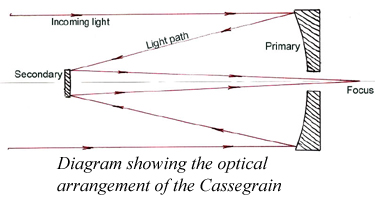
Cassegrain Arrangement
The eyepiece is at the back of the telescope. The hole in the centre of the mirror does not affect the viewing ability.
All large telescopes use the reflecting system. The largest telescope in the world has a 5 metre diameter concave mirror which requires many tonnes of glass, a considerable cooling time, and many hundred of hours of grinding to get it to a perfect shape. It was silvered with a few grams of aluminium.
You can be asked to draw the path the light takes from the source to reach the observer.
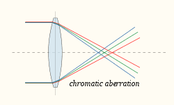
Aberration
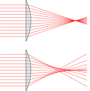
When using lenses or mirrors to make light travel a certain path, aberration occurs. This is when all of the light rays fail to combine at a single focus.
There are two types of aberration; spherical and chromatic.
Spherical aberration occurs when light is refracted, but not all onte the same point. As such the image loses definition and would appear to be out of focus as it has numerous focal points. The greater the distance the source is to the lens, the greater the spherical aberration.
Chromatic aberration occurs when light is refracted into different colours by different amounts. You can see that when light is split into a spectrum with a prism.
Telescopes
Radio and Optical Telescopes
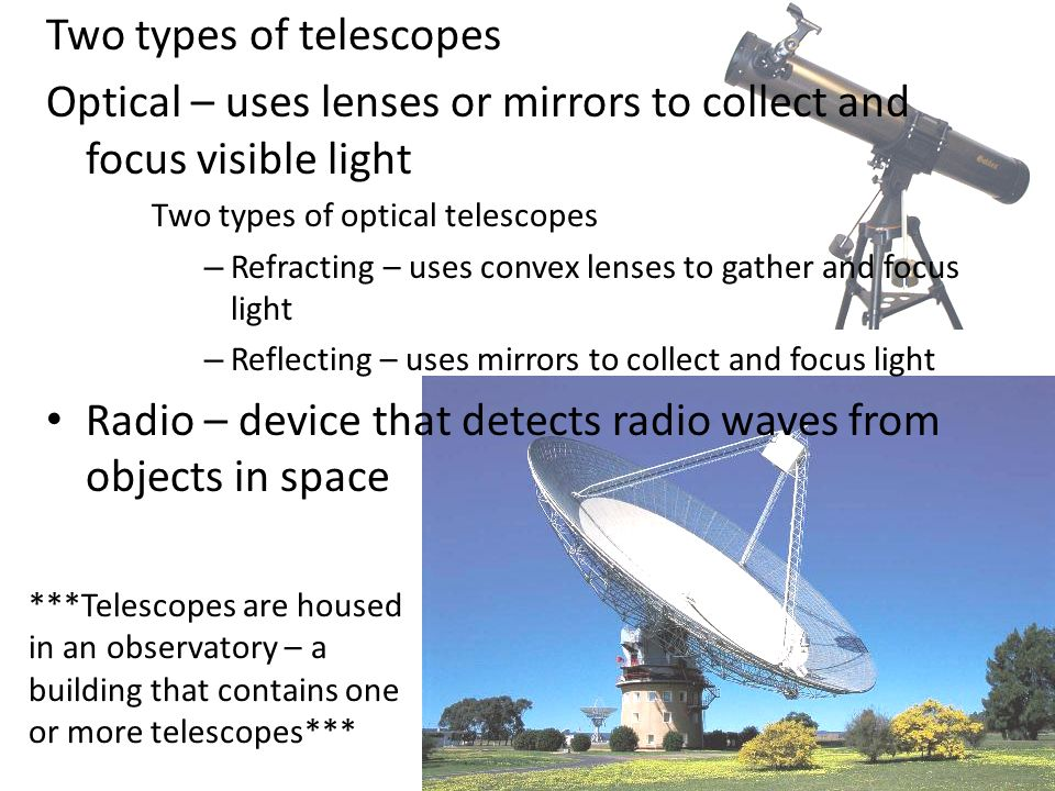
Both optical and radio telescopes have curved dishes reflect which collect electromagnetic radiation.
The location, resolving powers and positioning of different telescopes are vital for the information we can garner from them.
Having telescopes on the ground means that they are easily accessible, yet the light travelling through the atmosphere will affect the resolution to which we can see
Telescopes in space means there is no atmospheric interference, but it is very difficult to service due to its location.
Having a larger diameter lens means that a telescope has more collecting power/gather in more information. In addition, the larger the lens the higher the resolution which means the image is much more detailed and defined.
If the telescope uses reflection it can suffer from spherical aberration whereas a telescope that uses lenses suffers from chromatic aberration.