Current–Voltage Characteristics
Non-ohmic Resistors
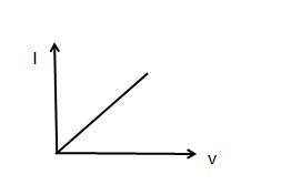
You need to know the current-voltage characteristics for an ohmic conductor, semiconductor diode and a filament lamp. Recall that an ohmic conductor obeys Ohm’s Law; V = IR. This is a linear relationship which goes through the origin (as seen below).
The current voltage graphs of each of the required components are shown below.
Ohmic Conductor.

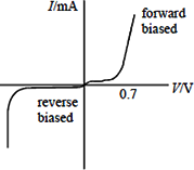
Semiconductor diode
The shape of the filament lamp or filament bulb is as follows:
An increase in the current/potential difference leads to an increase in the temperature. This causes increased movement of the ions in the filament. As such, there are more collisions between the flowing electrons. This means that there is an increase in the resistance as shown on the graph as the potential difference is not proportional to the current.
The shape of the diode is as follows:
A diode has a forward bias where there is initially high resistance and a small current until approx 0.7V, after which the resistance rapidly decreases.
The diode also has a reverse bias where there is a high resistance and almost zero current until the point where it breaks down. At this points the resistance is approximately zero and there is a very large current.
Examples
There are numerous questions that ask you to draw the shape of the I-V graph and explain the characteristics that you have drawn.
Studying.
Try and write down as much information on this topic as you can from memory! Try it a few times to see if you can improve.
Resistivity
Resistivity is a measure of how resistance an insulator is based upon how much space there is that the electrons travel through.
⍴ = resistivity (Ωm)
R = Resistance (Ω)
A = Cross-sectional area (m2)
L = Length (m)
Temperature
As the temperature increases, the resistance increases. This is because the ions gain energy and move more. This causes more collisions with the oncoming electrons which increases the resistance.
However not all electrical components have an increased resistance when the temperature increases. I present thermistors!
Thermistors
In thermistors the resistance decreases as the temperature increases. This is because they release more electrons at higher temperatures, this results in more charge carriers and a decreasing resistance.
Superconductivity
Superconductivity is a special application where the use of strong magnetic fields help to reduce the energy loss when transmitting electric power. They reduce the resistance to zero values which allows the current to be much higher than normal. It does this by lowering the temperature to a critical temperature at which point the conductor becomes a superconductor.
Uses for superconductors include; mri scanner, transformer, generator, maglev train, particle
accelerators, microchips and computers
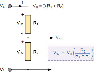
Potential Divider
A potential divider is used to supply a constant or variable potential difference from the power supply. Ultimately, it is a combination of resistors in series connected across a potential difference source.
Examples of Potential Dividers
Examples of potential dividers include, but are not limited to, variable resistors, thermistors and light dependent resistors (LDR).
Circuits
ResistanceIn a Circuit
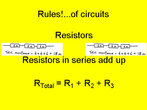
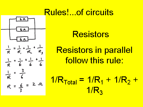
You need to be able to calculate the resistance of a circuit for resistors in series and parallel:
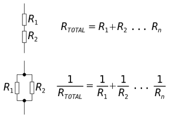
Note that for parallel you need to take the inverse or the reciprocal of your answer in order to have your final total resistance.
Energy And Power
Equations!!!
Energy = Current x potential difference x time
Power = Current x Potential difference = Current squared x Resistance = Potential difference squared divided by Resistance
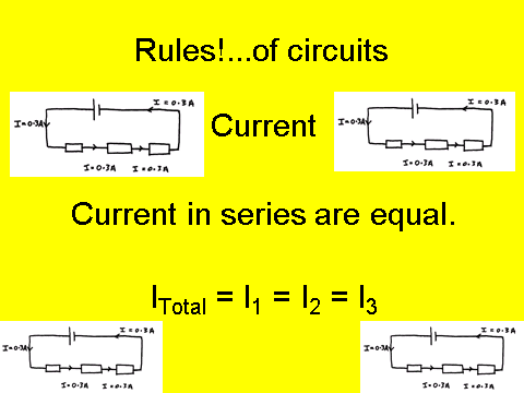
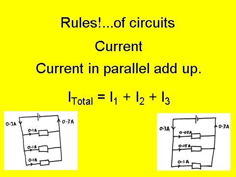
Rules of a Circuit
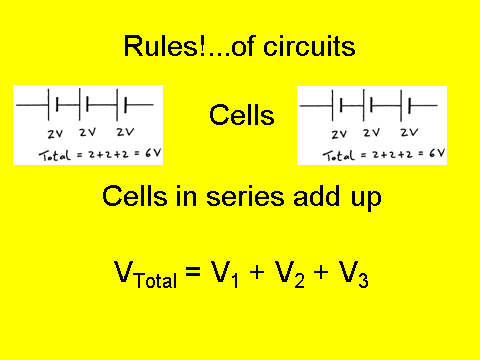
For identical cells in parallel - the potential difference remains the same. So if you have two 1.5V cells in parallel - the potential difference of the circuit is….1.5V
Conservation Rules
Charge and energy are always conserved in a circuit
Electromotive Force and Internal Resistance
Define Electromotive Force
Electromotive force is often referred to as emf.
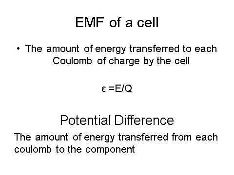
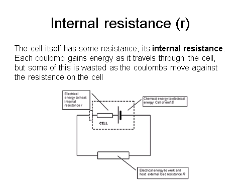
We can relate the emf and the internal resistance by the following relation:
Remember that emf is measured in volts.
Small ‘r’ is internal resistance and big ‘R’ is external resistance.
Examples
You will have to complete circuit calculations when the internal resistance is not negligible. Read the question carefully to ensure you know when you need to include internal resistance.
- What is the internal resistance of the battery?
- 1. 5