Magnetic Fields
Magnetic Flux Density
Force On a Wire
Magnetic force can be calculated via this equation which is given in your exam:
Force = Magnetic flux density x current x length of wire
F = B x I x l
F = Force, Newtons (N)
B = Magnetic flux density, Tesla (T)
I = Current, Amps (A)
l = length of wire in the magnetic field, metres (m)
A tesla is the strength of a magnetic field that produces a force of 1 N in a 1m wire with a current of 1A.
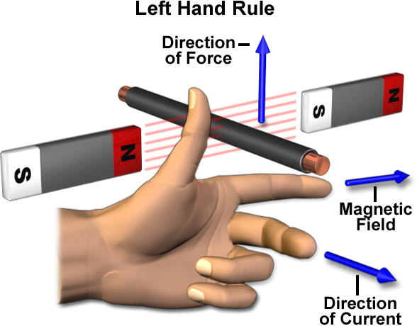
Fleming’s Left Hand Rule
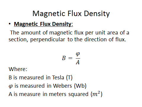
Magnetic Flux Density
Moving Charges in a Magnetic Field
Force
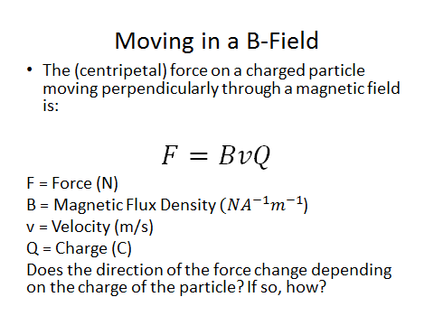
Positive and Negative Charges
Remember that opposites attract and like charges repel.
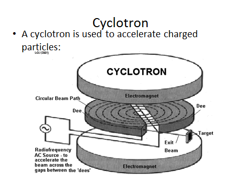
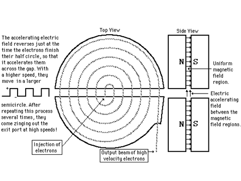
Circular Paths

Magnetic Flux and Flux Linkage
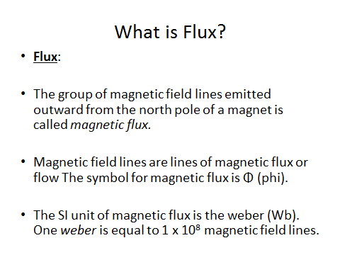
Magnetic Flux

ɸ = Magnetic Flux (Weber - Wb)
__B __= Magnetic flux density (T)
A = Area (m2)
Magnetic flux is the product of the magnetic flux density and the area that it is travelling through.
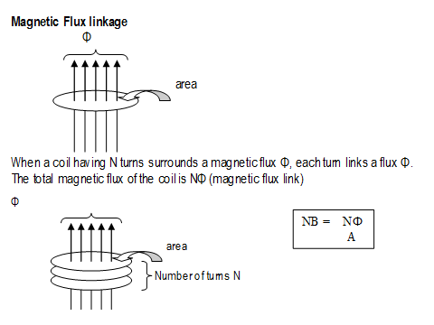
Magnetic Flux Linkage
The flux linkage includes how many turns of wire are cutting through the flux lines.
N = Number of turns.
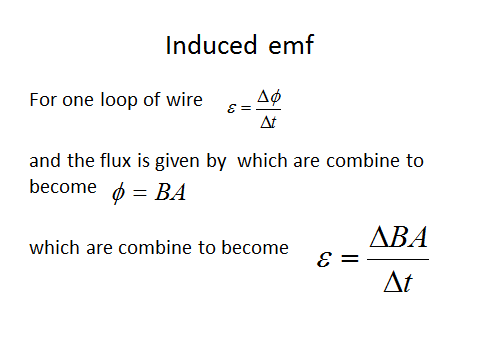
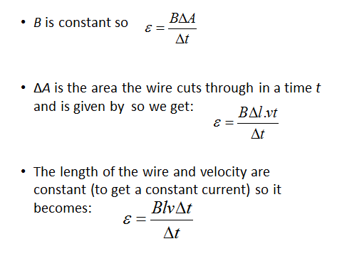
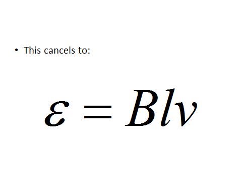
Electromagnetic Induction
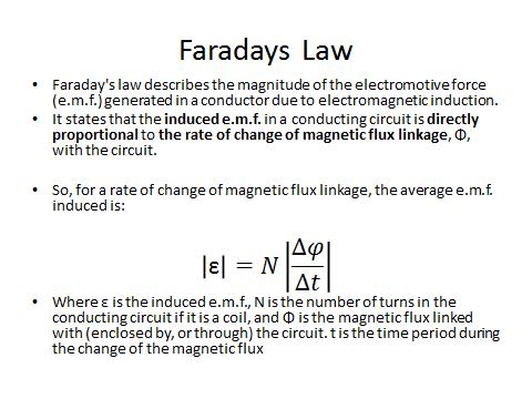
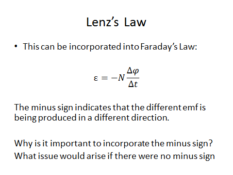
Laws
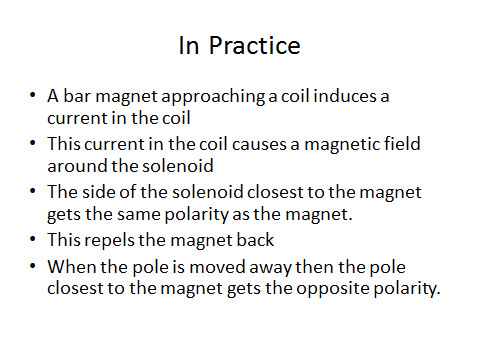
Application
Induced Emf 2
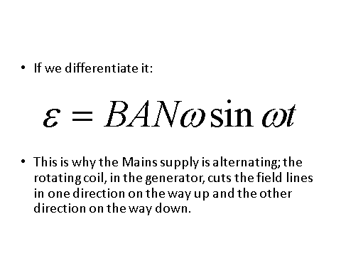
Above we have induced emf in a coil rotating uniformly in a magnetic field.
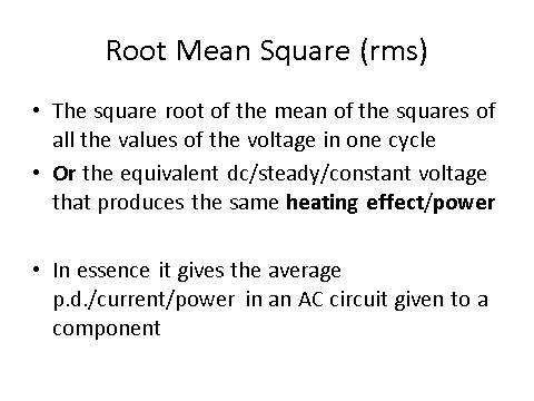
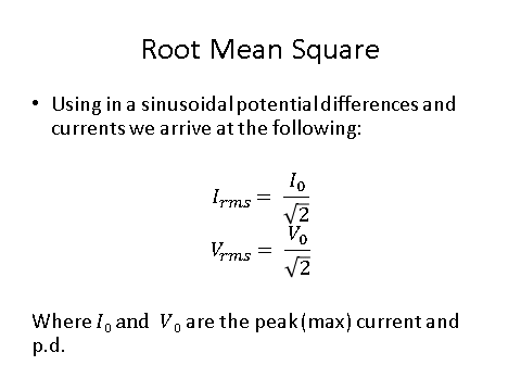
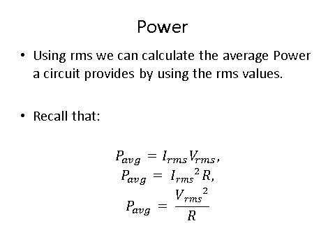
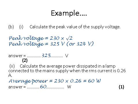
Alternating Currents
Applications
Oscilloscope
When reading an oscilloscope you need to know the following:
The y-axis represents potential difference (V). Normally one square is 1V but the scale can change so read the question carefully.
The x-axis represents the time period (s) of the wave. Again, the scale for each square can change so read the question carefully.
The middle line represents zero volts.
The peak to peak reading is twice the amplitude.
For a DC voltage you will get a straight line whereas an AC voltage will give you a sinusoidal wave.
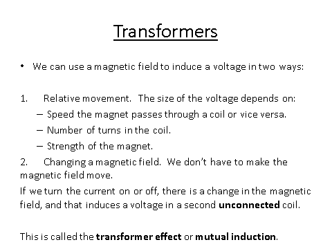
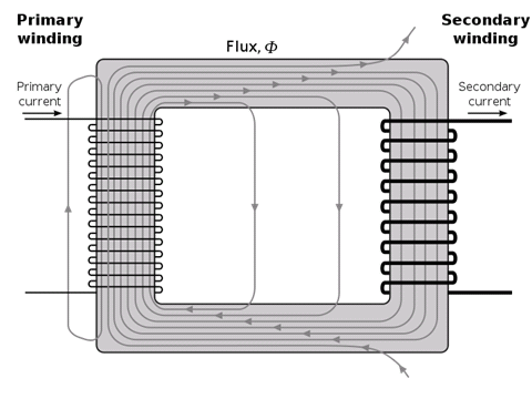
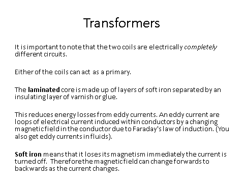
The Operation of a Transformer
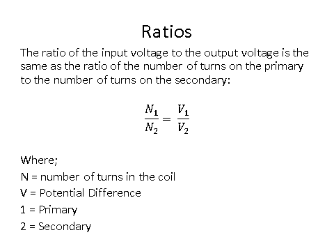
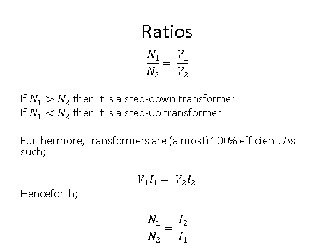
Transformer Equation
Eddy Currents
Inefficiencies
- A lamp rated at 12V 60W is connected to the secondary coil of a step-down transformer and is at full brightness. The primary coil is connected to a supply of 230 V. The transformer is 75% efficient. What is the current in the primary coil?
- Your answer should include: 0.35A / 0.35
Magnetic Flux & Flux Linkage
Magnetic Flux
ɸ = Magnetic Flux (Weber - Wb)
B = Magnetic flux density (T)
A = Area (m2)
Magnetic flux is the product of the magnetic flux density and the area that it is travelling through.
Magnetic Flux Linkage
The flux linkage includes how many turns of wire are cutting through the flux lines.
N = Number of turns.