Refraction Diffraction & Interference
Interference
Monochromatic
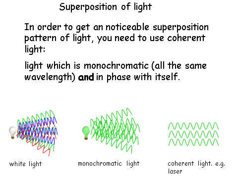

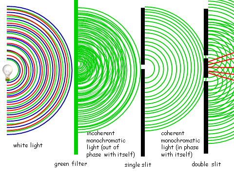
This last diagram shows how to get monochromatic coherent light in order to put it through a double slit in order to see the interference patterns.
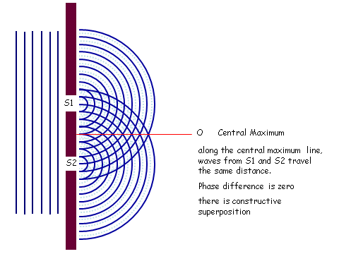
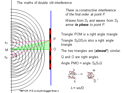
Double Slit
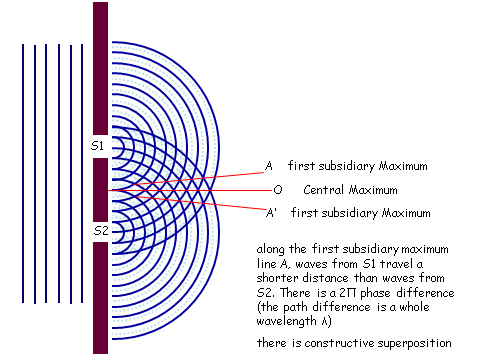
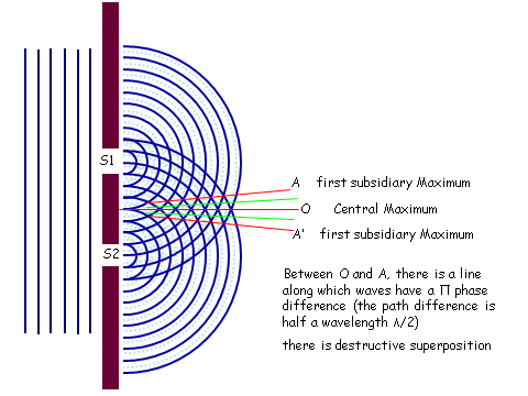
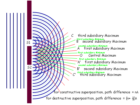
When light travels through a double slit, the waves diffract and start to interfere with each other. A screen at a given distance away will show the interference pattern. At some points there will constructive interference and at some points destructive interference.
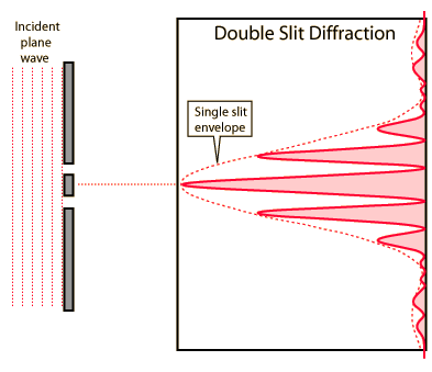
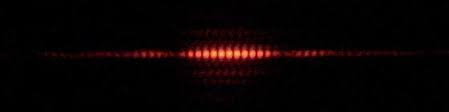
The interference pattern recorded looks something like this:
Fringe Spacing
Ultimately we get:
In practice it looks like this:
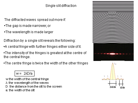
To calculate the fringe spacing we use the following relationship:
w = Fringe spacing (m)
= Wavelength (m)
s = distance between the slits (m)
D = Distance between the slits and the screen (m)
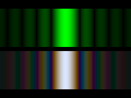
Notice that for white light the colours are splits, but there is a central part which remains white. Also notice how the intensity decreases as you move away from the central maximum.
Using Lasers
Using lasers can be dangerous as they can damage ones eyes and using them safely is essential.
When using a laser ensure you take care of the following:
Diffraction
Single Slit Diffraction
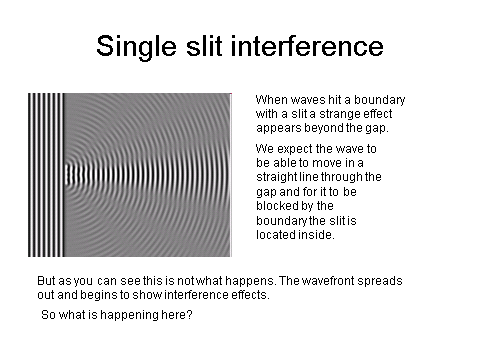
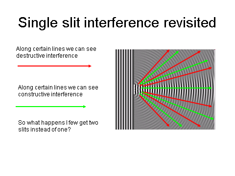
Single Slit Properties
Derivation of Single Slit Formula
Part 1:
Part 2:
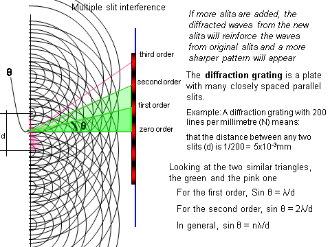
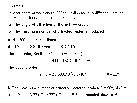
- A laser beam of wavelength 550 nm is directed at a diffraction grating with 500 lines per millimetre. Calculate the angle of diffraction for the first two orders.
- Your answer should include: 16 / 33
Explanation: First order: 16 Second order: 33 - For the same set up as in question 1, calculate the maximum number of diffracted patterns produced.
- 3
Explanation: 3 orders
Refraction
RefractionIndex
The refractive index of a substance is a ratio of the speeds of light in the different media.
The refractive index of a substance is given as:
Where;
n = refractive index
c = speed of light in a vacuum
cs = speed of light in the substance
The refractive index of air has a value of 1. Remember this as students often forget this helpful pointer.
Snell’sLaw
The above relation is for when light enters into a medium, but what happens if it goes over a boundary between two different media?
Snell found a relation, something we now call Snell’s Law:
Where;
n1 = refractive index of the first medium
= the first refracted angle
n2 = refractive index of the second medium
= the second refracted angle
TotalInternal Reflection
Total internal reflection is a phenomena that occurs when a wave is completely reflected between boundaries of the same medium. This means that light stays within the confines of the medium.
For total internal reflection to occur the angle that the light makes at the boundary must be at a critical angle:
Uses of Cladding
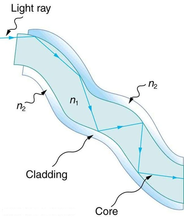
Cladding is used as an insulating material around the medium where total internal reflection is taking place to help the light totally internally reflect.
Introducing cladding can help to reduce the critical angle (see above equation). This is particularly useful in fibre optic cables. Fibre optic cables are used for people to connect to the internet at very high speeds. The cladding means that more people have access to the information as it is easier to send.
Dispersion
Dispersion occurs when information does not all arrive at the same time. Here we have two types of dispersion; material and modal.
Material dispersion occurs when different wavelengths propagate at different velocities which is dependent on the refractive index of the material used in the fibre optic cable.
Modal dispersion occurs when the signal is spread in time because the propagation velocity of the optical signal is not the same for all modes of the signal.
Pulse Broadening and Absorption
As the signal travels down the cable, some of the signal will be lost due to absorption by the cladding.
As such, in long cables, there are points where the pulse is enhanced and ‘re-energised’. This allows the signal to travel long distances and to not be completely absorbed by the cable/cladding.
- A ray of light is totally internally reflected within some glass. The glass has no cladding and is exposed to the outside air. Calculate the critical angle when the refractive index of glass is 1.7?
- 36