Circuits
Circuit Symbols
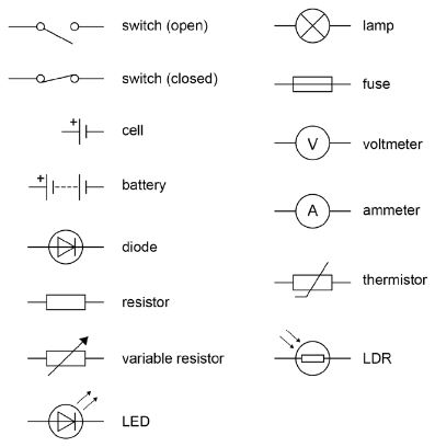
All circuit diagrams use a set of established symbols. You need to be familiar with the circuit symbols below to understand the circuit diagrams that you may encounter in your exam.
Series and Parallel
Circuits can be categorised as series or parallel.
Series Circuits
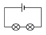
In a series circuit:
- There is only one path around the circuit
- If one component breaks, all the other components will stop working
- More bulbs in series will cause the brightness of all the bulbs to decrease
- Switches will control all the bulbs together
Parallel Circuits
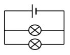
In a parallel circuit:
- There is more than one path around the circuit
- If one component breaks, the others stay on
- More bulbs added in parallel will be the same brightness as the original bulb
- Switches (on branches) will control bulbs individually
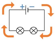
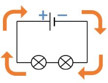
Current
Current is the flow of electrons (charged particles) around a circuit. Electrons are repelled from the negative end of the cell and attracted to the positive end.
Current is measured using an ammeter which is connected in series with the circuit.
The flow of charge can be calculated using this equation (you DO need to remember this for your exam):
Q = It
Q = flow of charge (Coulombs, C)
I = current (Amps, A)
t = time (s)
Worked Example
A charge of 16C passes through a bulb in 5s. Calculate the current through the bulb
Q = It
I = Q ÷ t
I = 16 ÷5
I = 3.2A
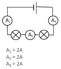
Series
In a SERIES circuit, the current is always the same, no matter where you place the ammeter.
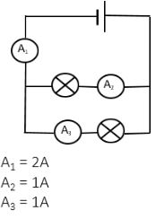
Parallel
In a PARALLEL circuit, the current splits and divides down each branch of the circuit.
Potential Difference (Voltage)
Potential difference refers to the difference in charge between the positive and negative ends of the cell/battery. The bigger the potential difference, the bigger the force on the electrons – pushing them around the circuit.
Potential Difference is measured in Volts (and commonly called voltage). It is measured using a voltmeter which is placed in parallel with the component across which it is measuring the voltage.
The relationship between energy, potential difference and charge is described by this equation (you DO need to remember this for your exam):
E = VQ
E = Energy transferred (Joules, J)
V = Potential difference (Volts, V)
Q = flow of charge (Coulombs, C)
Worked Example
The energy transferred to a bulb is 360J when 64C of charge passes through it. Calculate the potential difference across the bulb.
E=VQ
V = E ÷ Q
V = 360 ÷ 64
V = 50V
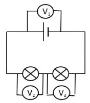
Series
In a SERIES circuit, the voltage is shared out between each component.
Parallel
In a PARALLEL circuit, each branch of the circuit receives the same voltage as the power supply.
Summary
When analysing circuits it is very important to remember the ‘laws’ for the behaviour of potential difference and current in series and parallel circuits:
Current:
- In a SERIES circuit, the current is always the same, no matter where you place the ammeter
- In a PARALLEL circuit, the current splits and divides down each branch of the circuit
Potential Difference:
- In a SERIES circuit, the voltage is shared out between each component
- In a PARALLEL circuit, each branch of the circuit receives the same voltage as the power supply
- Calculate the charge if 5A of current flows for 3s.
- 15
- Calculate the current if 75C of current flows for 25s.
- 3
- Calculate the energy supplied by a 6V torch battery if 1500C of charge flows.
- 9000
- Calculate the charge that flows if 4800J of energy is supplied in a circuit at 240V?
- 20