Resistance
Resistance
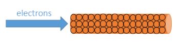
Resistance is opposition to the flow of current. A high resistance means it is harder for current to flow through. A low resistance means current will flow through more easily.
Resistance is measured in Ohms (Ω).
Ohm’s Law
Ohm’s law states that current is directly proportional to potential difference (providing the temperature remains constant).
It can be summarised in the equation (you DO need to remember this equation for your exam):
Voltage = Current x Resistance
V = I x R
V = Voltage (Volts)
__I __= Current (Amps)
R = Resistance (Ω)
Measuring Resistance
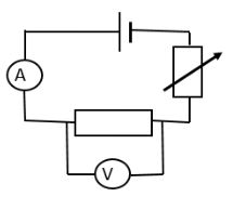
To measure the resistance of a component, a standard test circuit is used to measure the current flowing through the component and the potential difference across it. The equation above can then be used to calculate resistance
Required Practical – Resistance of a Wire
You need to be familiar with the practical procedure used to investigate the factors affecting the resistance of a wire.
The factors affecting the resistance of a wire are:
- Length
- Cross-sectional area (thickness)
- Material
- Temperature
They can be investigated using a standard test circuit:
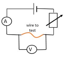
If investigating length:
- Measure and record the current and potential difference across the wire
- Calculate resistance using V=IR
- Repeat for different lengths of wire (keeping the material, thickness and temperature constant)
The same method can be used to investigate the other variables.
When the results are analysed, the following patterns should be observed:
- Length - The longer the wire the higher the resistance. This should be a directly proportional relationship. As the wire length is increased, the same potential difference is driving current through a longer length and so less electrons will flow.
- Cross -sectional area – The thinner the wire, the greater the resistance. A thinner wire has less electrons available to move, so less current will flow when the same potential difference is applied.
- Temperature – The higher the temperature of the wire, the greater the resistance. As temperature increases, the atoms in the wire have more kinetic energy and vibrate faster, making it harder for electrons to pass through
- Material – Different materials have different resistivity. This is not a continuous variable and so, unlike the previous three, could only be plotted on a bar chart.
Possible causes of error in this investigation include:
- Inaccurate measurement of wire – the crocodile clips used to connect the wire in the circuit are a few mm wide and this could lead to the length of wire conducting electricity being slightly shorter than intended. This could be improved by using thinner contacts.
- Temperature – it is difficult to control the temperature of the wire and, as the investigation takes place, it is likely to heat up, which affects the resistance of the wire. This could be improved by letting the wire cool down to room temperature in between each measurement.
Resistors in Series and Parallel
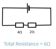
Resistors in Series
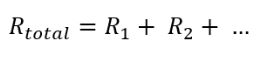
The total resistance increases as more resistors are added in series. The same voltage is being used to push current through a harder circuit, therefore less current travels.
The resistance can be calculated using the equation (you do NOT need to remember this equation):
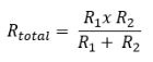
Resistors in Parallel
The total resistance decreases as more resistors are added in series. Each branch of a parallel circuit receives the same voltage and so, overall, more current is pushed around the circuit.
The resistance can be calculated using the equation (you do NOT need to remember this equation):
IV Graphs
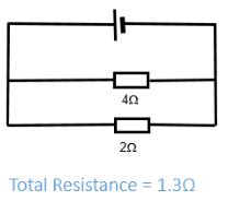
A current-voltage (or IV) graph shows how resistance varies for a component. The negative section of the graph shows what happens if the direction of the current is reversed.
A fixed resistor obeys Ohm’s law and produces a directly proportional IV graph. The graph is symmetrical as the same relationship exists when current flows in the opposite direction through the resistor.
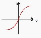
A filament bulb gets hot as current flows through it. This causes the resistance to increase and the IV graph to curve. The graph is symmetrical as the same relationship exists when current flows in the opposite direction through the bulb.
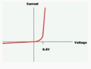
A diode only lets current flow in one direction. The IV graph has no current flowing in the reverse direction.
Components
You need to be familiar with the following components – their circuit symbol and their function.
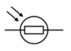
- LDR - Light Dependant Resistor. Resistance decreases when light intensity increases
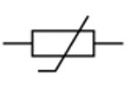
- Thermistor - Resistance decreases as the temperature increases
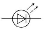
- LED - Light Emitting Diode. Glows when current flows through it in the forward direction
- What is the resistance of the heating element in an electric kettle that uses mains voltage (230V) and a current of 10A?
- 23
- A 12V filament light bulb has a resistance of 60Ω. What current flows through the bulb?
- 2
- A hairdryer using mains voltage (230V) has a current of 5A flowing through the motor. What is the resistance of the motor?
- 46
- A remote controlled car uses three 1.5V batteries. If its resistance is 15Ω, what current flows through it?
- 3
- A 6V battery is used to power a portable speaker that has a resistance of 4Ω. What current flows through the speaker?
- 1.5