Electromagnetic Effects
The Motor Effect
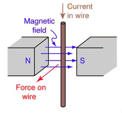
When a current flows through a wire, it produces a magnetic field around the wire. If the current-carrying wire is near another magnet it will experience a force (attraction/repulsion)
Fleming’s Left Hand Rule
The magnetic field, current and force act at right angles to one another. Fleming’s left hand rule can predict the direction of motion.
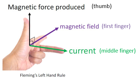
- Thumb – Direction of force
- First Finger – Direction of magnetic field (North to South)
- __Second (middle) finger __– Direction of current
Electric Motor
An electric motor uses a coil of wire in a magnetic field. The current is flowing in different directions in each side of the coil. This means that (according to Fleming’s Left Hand Rule) one side of the coil will move upwards and the other side will move downwards)
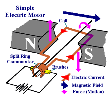
As the sides of the coil experience opposite forces, the coil will rotate. The coil is connected to the circuit using brushes and a split-ring commutator. The brushes allow electricity to be conducted to the coil while also allowing it to move. The split-ring ‘breaks’ and re-connects the circuit every half turn to allow constant rotation.
Electric motors can be made more powerful by:
- Increasing the current
- Increasing the length of wire in the magnetic field
- Increasing the strength of the magnetic field
Magnetic Flux Density
Magnetic flux density is a measurement of the strength of a magnetic field. (You do NOT need to remember this equation for your exam)
F = B I L
F = force (N)
B = magnetic flux density (Tesla, T)
__I __= current (A)
L = Length (m)
Worked Example
A wire has a current of 2.2A flowing through it as it passes through a magnetic field of 0.5T. What force will the 0.25m wire experience?
F=BIL
F = 0.5 x 2.2 x 0.25
F = 0.275N
Electromagnetic Induction
When a wire is moved through a magnetic field, electric current is induced in the wire
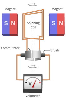
Alternator
Electricity can be generated by rotating a magnet inside a coil of wire. This induces a current in the wire. As the magnetic field is changing direction repeatedly (as it turns), the direction of the induced current also changes. Therefore, alternating Current (AC) is produced. This type of generator is called an alternator.
Dynamo / DC Generator
A dynamo generates Direct Current (DC). It is similar to the alternator except it has a split ring commutator, which means that current is only produced in one direction.
This DC varies from 0 to a positive value. This is different to DC from a battery which is a constant positive value.

Transformers
A transformer is a device which is used to increase or decrease voltage (potential difference). It consists of two coils of wire (not connected together) wrapped around an iron core.
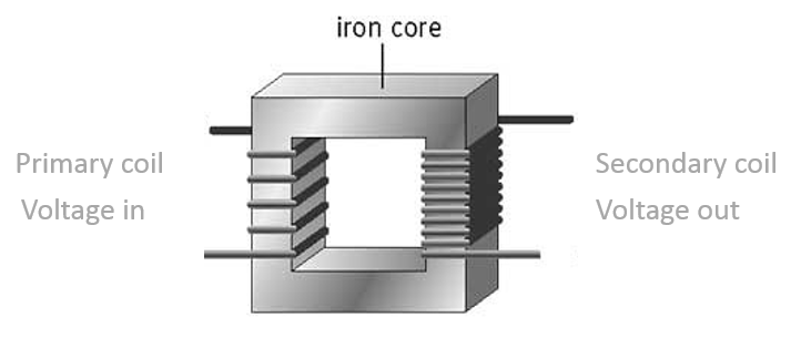
An alternating current in the primary coil creates an alternating magnetic field around the iron core. The secondary coil is in the alternating magnetic field. This induces an alternating current in the secondary coil. Transformers do not work with DC as the magnetic field does not change.
- a STEP UP transformer increases the voltage. It has more turns on the secondary coil.
- a STEP DOWN transformer decreases the voltage. It has less turns on the secondary coil.
The relationship between voltage and the number of turns on the primary and secondary coil can be described using this equation (you do NOT need to remember this equation for your exam):
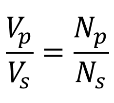
V = voltage
N = number of turns
P = primary coil
S = secondary coil
Worked Example
A transformer has 200 turns on its primary coil and 50 turns on its secondary coil. The input voltage is 920V.
Vp/Vs = Np/Ns
920/Vs = 200/50
Vs = 920/4
Vs = 230V
Transformer Efficiency
Transformers are almost 100% efficient. If 100% efficiency is assumed:
Vp x Ip = Vs x Is
V = voltage
I = current
P = primary coil
S = secondary coil
Worked Example
A transformer is used to step down an alternating voltage of 230V to 12V for a 2.5A light bulb. Assume that the transformer is 100% efficient and calculate the current in the primary coil of the transformer.
Vp = 230V
Ip = ?
Vs = 12V
Is = 2.5A
230 x Ip = 12 x 2.5
Ip = (12 x 2.5) ÷ 230 = 0.13A
National Grid
The National Grid is a network of wires and pylons connecting power stations and consumers together.
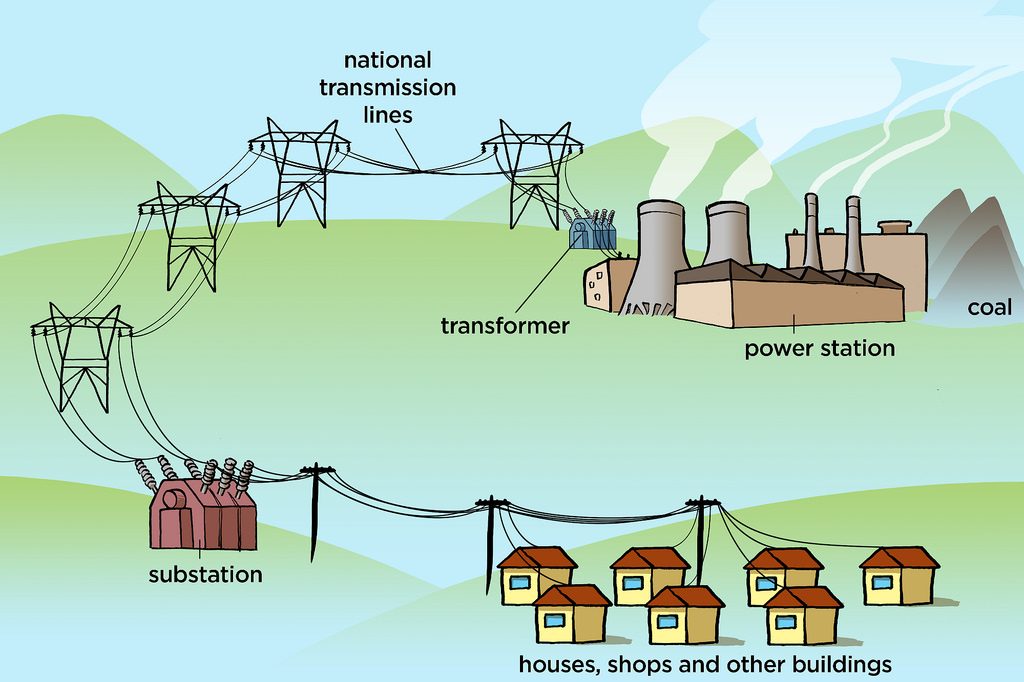
Every power station feeds into the grid and every consumer takes electricity from the grid. Transformers are used to step up voltage from power station to the grid and to step down voltage from the grid to homes (230V)
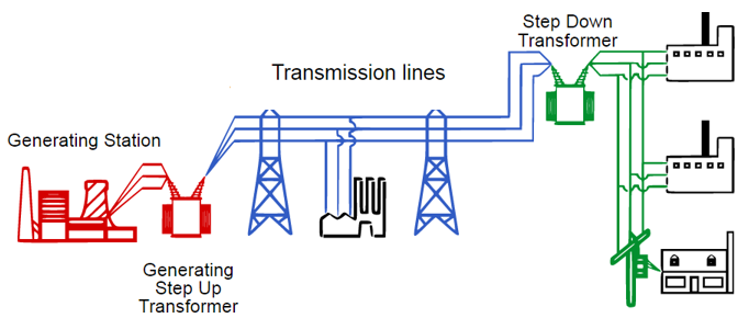
High voltages are used between pylons (400,000 V) so that less energy is lost (high voltage = low current at constant power [P=IV])
- A step down transformer for some Christmas lights has 600 turns on the primary coil and 30 turns on the secondary coil. If it is connected to the mains (230V), what voltage is supplied to the lights?
- Your answer should include: 11.5V / 11.5
Explanation: 11.5V - A transformer with 400 turns on it’s primary coil is used to step down the mains voltage (230V) to 30V. How many turns are on the secondary coil?
- 52
- A magnet is pushed into a wire and 2A of current is induced in the wire. What is produced when the magnet is pulled out of the wire?
- Your answer should include: -2A / -2
Explanation: -2A