Light
Reflection
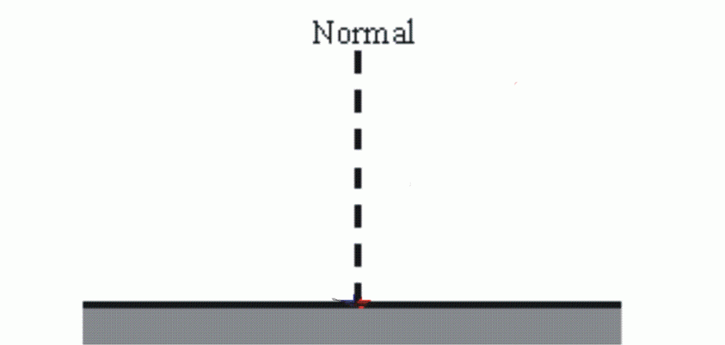
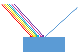
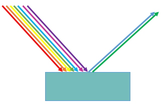
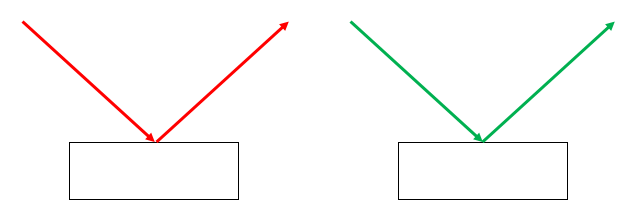
When light is reflected, the angle of incidence always equals the angle of reflection:
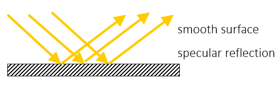
If the surface is smooth, then every ray of light is reflected at the same angle and a reflection can be seen (eg mirror). This is called specular reflection.
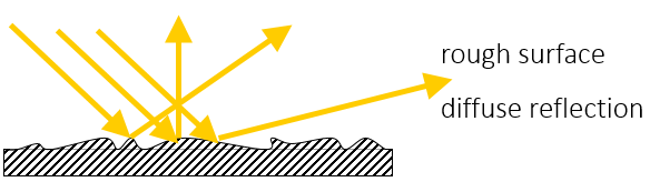
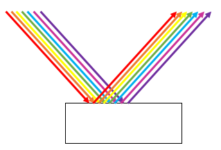
If the surface is rough, then, although each ray of light obeys the law of reflection where it hits the surface, the rays of light do not all hit the surface at the same angle so they are not all reflected at the same angle as each other. This is called diffuse reflection, the object can be seen as some light will be reflected into the eye, but a reflected image can not be seen.
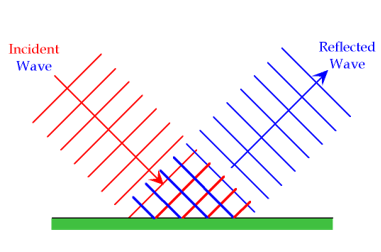
Light travels as electromagnetic waves. Reflection of waves can be shown with a wave front diagram. The law of reflection still applies.
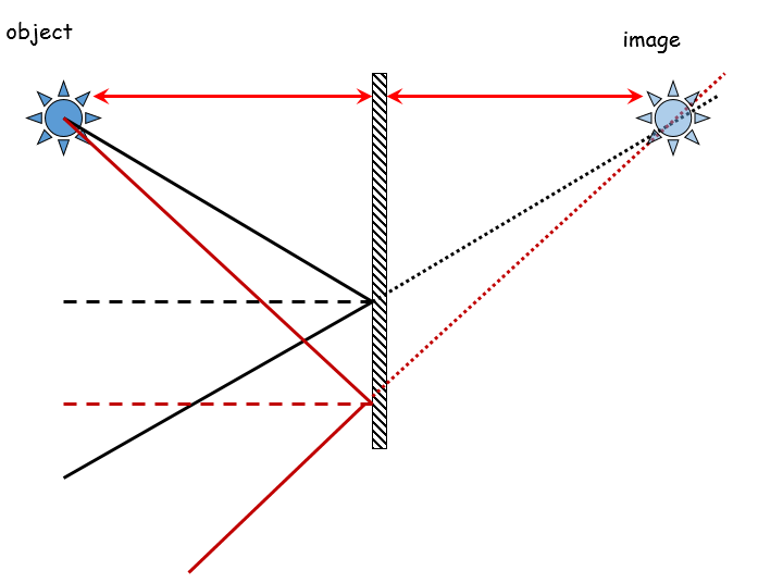
To find the position of an image from a mirror, you need to construct a ray diagram with the angles drawn as accurately as you can. Draw 2 (or more) rays of light from your object to the mirror (at different angles). Draw the normal (line at 900 to mirror) for each ray and then measure the angle of incidence. Draw the reflected rays at the same angle using a protractor and then extend the reflected rays ‘behind’ the mirror. The place where there lines cross is the position of the image.
The image should be the same distance behind the mirror as the object is in front.
Light
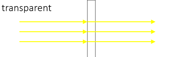
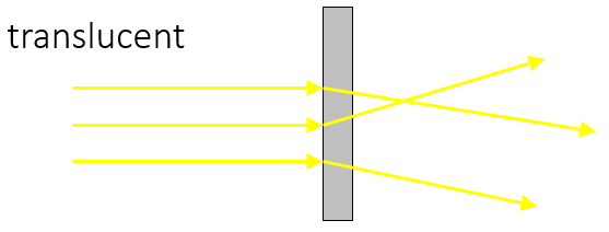
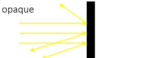
When light encounters a material, it could be transmitted (pass through), reflected, absorbed or scattered by the material:
Refraction
Refraction happens due to a change in speed. As light travels from one material to another, it changes speed
If the light enters parallel to the normal, the change in speed does not produce a noticeable effect. If the light enters at an angle, the change in speed results in a change in direction of the light.
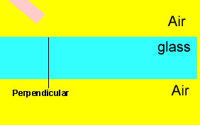
As the wave front travels from one material to another at an angle, not all of the wave hits the boundary and changes speed at the same time. This causes the change in direction:
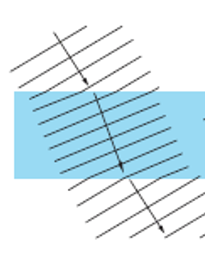
In the diagram, the refracted wave fronts are closer together than the incident wave fronts. The waves have the same frequency but travel at different speeds, so they have different __wavelengths __(v=fλ).
Apparent Depth
If you are looking at an object that is under water, light is travelling from a source, reflecting off the object and travelling to your eye. As the light leaves the water, it is refracted. Your brain assumes that the light travelled in a straight line, so the object appears to be higher in the water than it actually is. The Archer fish takes this into account when it spits water at insects!

Lenses
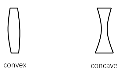
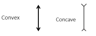
A lens is a curved material that uses refraction of light to form an image. A convex (or converging) lens is thicker in the middle than the edges. A concave (or diverging) lens is thinner in the middle than the edges.
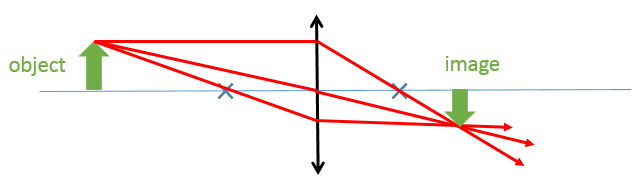
Convex (Converging) Lens
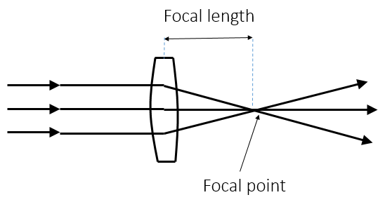
A convex lens causes parallel rays of light to converge to a point. The point where the rays meet is the focal point or principal focus. The distance from the centre of the lens to the focal point is the focal length.
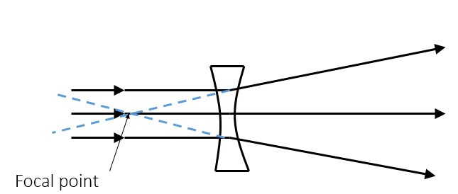
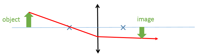
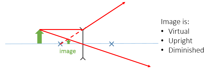
Concave (Diverging) Lens
A concave lens causes parallel rays of light to spread out (diverge). The point where the rays __appear to come from __is the focal point:
Magnification = image height ÷ object height
Constructing Ray Diagrams
When drawing ray diagrams:
- Draw straight lines using a ruler
- Use arrows to show the direction
- Draw to scale
- Use correct symbols for convex and concave lenses:
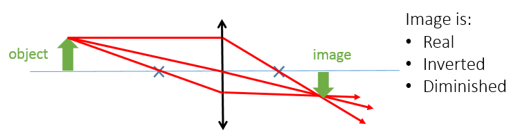
Draw 3 rays of light to construct your image:
1 - Parallel to axis – refracted through focal point
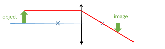
2 - Straight through the centre of the lens (not refracted)
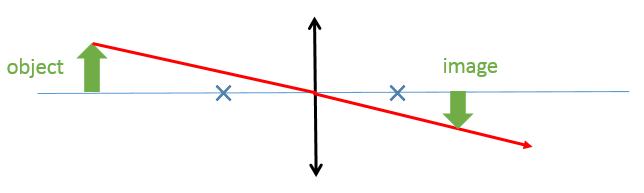
3 - Through the focal point before the lens – refracted parallel to axis
- The image is produced where the 3 rays cross
Use the following words to describe images:
Real – the image could be formed on a screen (the rays of light actually meet at that point)
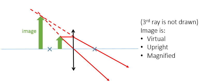
Virtual – the image could not be formed on a screen (the rays of light only appear to come from that point
Inverted – upside down
Upright – the same way up as the object
Diminished – smaller than the object
Magnified – larger than the object
Example ray diagrams:
Worked Example
An object which is 5cm high is 8cm away from a convex lens of focal length 5cm. Construct a ray diagram to calculate the height of the image. Calculate the magnification of the lens.
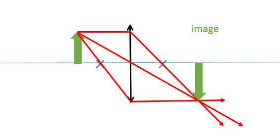
Image is:
- Real
- Inverted
- Magnified
- If diagram is drawn to scale, the image is approximately 8cm
- Magnification = 8÷ 5 = 1.6
Colour
‘White’ light is made up of different colours called a spectrum. The colour of the light depends on the wavelength of that light. A prism can be used to separate white light into a spectrum as the different wavelengths (colours) are refracted by different amounts.
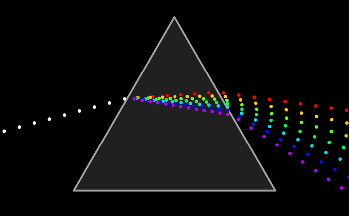
The colours of the spectrum are:
- Red
- Orange
- Yellow
- Green
- Blue
- Indigo
- Violet
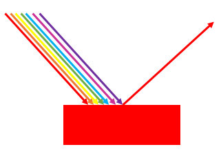
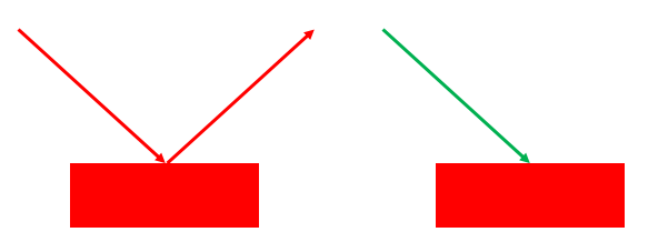
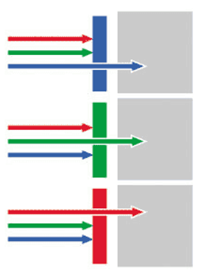
Objects appear to be certain colours because they reflect some wavelengths of light and absorb others.
- White light (containing all colours) hits the red object
- Red light is reflected from the object
- All other colours are absorbed by the object
- The object appears red
- White light (containing all colours) hits the blue object
- Blue light is reflected from the object
- All other colours are absorbed by the object
- The object appears blue
Other colours appear when different wavelengths are reflected in different amounts
A white object appears white because all wavelengths are reflected
A black object appears white because no light is reflected

Coloured Lights
Objects can appear different colours under coloured lights. Under red light, a red object will still appear red as it will reflect red light. Under green light, the red object will appear black as the green light will be absorbed.
A white object reflects all colours. Under red light, the white object will appear red. Under green light, the white object will appear green
Colour Filters
A colour filter absorbs some wavelengths of light and transmits others. A blue filter allows blue light to pass through but absorbs other colours
- What is the name of a lens which converges rays of light to a focal point?
- convex
- What is the name of a lens which diverges rays of light from a focal point?
- concave
- What colour will a yellow flag appear to be under red light?
- black
- What colour will a white flag appear to be under red light?
Explanation: red- What is the name for the effect of light changing direction as it travels from one medium to another?
- refraction