Investigate Different Types of Non-Ohmic Resistors
Experimental Set Up
This experiment is set up to confirm the results shown in the previous lesson.
It investigates two non-ohmic resistors as well as an ohmic resistor.
Method
Experiment 1: The characteristic of a resistor
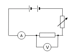
- Connect the circuit. It may be helpful to start at the positive side of the battery or power supply. This may be indicated by a red socket.
- Connect a lead from the red socket to the positive side of the ammeter.
- Connect a lead from the negative side of the ammeter (this may be black) to one side of the resistor.
- Connect a lead from the other side of the resistor to the variable resistor.
- Connect a lead from the other side of the variable resistor to the negative side of the battery. The main loop of the circuit is now complete. Use this lead as a switch to disconnect the battery between readings.
- Connect a lead from the positive side of the voltmeter to the side of the resistor the ammeter is connected to.
- Connect a lead from the negative side of the voltmeter to the other side of the resistor.
- Record the readings on the ammeter and voltmeter in a suitable table.
- Adjust the variable resistor and record the new ammeter and voltmeter readings. Repeat this to obtain several pairs of readings.
- Swap the connections on the battery. Now the ammeter is connected to the negative terminal and variable resistor to the positive terminal. The readings on the ammeter and voltmeter should now be negative.
- Continue to record pairs of readings of current and potential difference with the battery reversed.
- Plot a graph with a) ‘Current in A’ on the y-axis, b) ‘Potential difference in V’ on the x-axis.
As the readings include negative values the origin of your graph will be in the middle of the graph paper. You should be able to draw a straight line of best fit through the origin. This is the characteristic of a resistor.
Experiment 2: The characteristic of a lamp
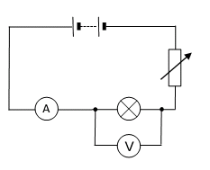
- Swap the leads on the battery back to their original positions.
- Replace the resistor with the lamp. If you are making the circuit from the beginning, follow steps 1-7 in the procedure for the resistor above. For these instructions, use a lamp in place of the resistor.
- The lamp will get hot. Take care not to touch it.
- Follow steps 8‒11 in the procedure for the resistor above. Remember to swap the leads on the battery to obtain negative readings.
- Plot a graph with: a) ‘Current in A’ on the y-axis, b) ‘Potential difference in V’ on the x-axis.
Again the origin will be in the middle of the paper. Draw a curved line of best fit for your points.
Experiment 3: The characteristic of a diode
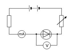
- Swap the leads on the battery back to their original positions.
- If you can, reduce the battery potential difference to less than 5 V.
- Remove the lead from the positive side of the battery. Connect it to the extra resistor labelled P.
- Connect the other end of resistor P to the positive side of the battery.
- Replace the ammeter with a milliammeter or change the setting on the multimeter.
- Replace the lamp with the diode. Connect the positive side of the diode to the millimetre.
- Repeat steps 1–6 above to obtain pairs of readings of potential difference and current for the diode.
- Plot a graph with: a) __‘Current in A’ on the y-axis, __b) ‘Potential difference in V’ on the x-axis.
The origin will probably be in the middle of the bottom of your graph paper. There should not be any negative values of current.
Results
The graphs are shown in the previous lesson. It is vital you commit these methods to memory, you can never be sure which experiment will be required for the exam. Whilst studying hard, notice the similarities in each experimental set-up and method.